11/23/14

TeensyDSC – it works!

So last night I was finally able to test my custom digital setting circles setup on my AD12… it worked great!  I used the Astrosystems 10K encoder kit with the TeensyDSC and SkySafari on my iPad.  Here’s the photos of my setup:

My Digital Settings Circles setup using SkySafari on the iPad

My Digital Settings Circles setup using SkySafari on the iPad

Alt encoder and Wireless DSC module powered by a USB battery pack

Alt encoder and Wireless DSC module powered by a USB battery pack


11/17/14

A working basic TeensyDSC board

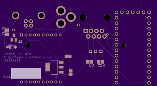
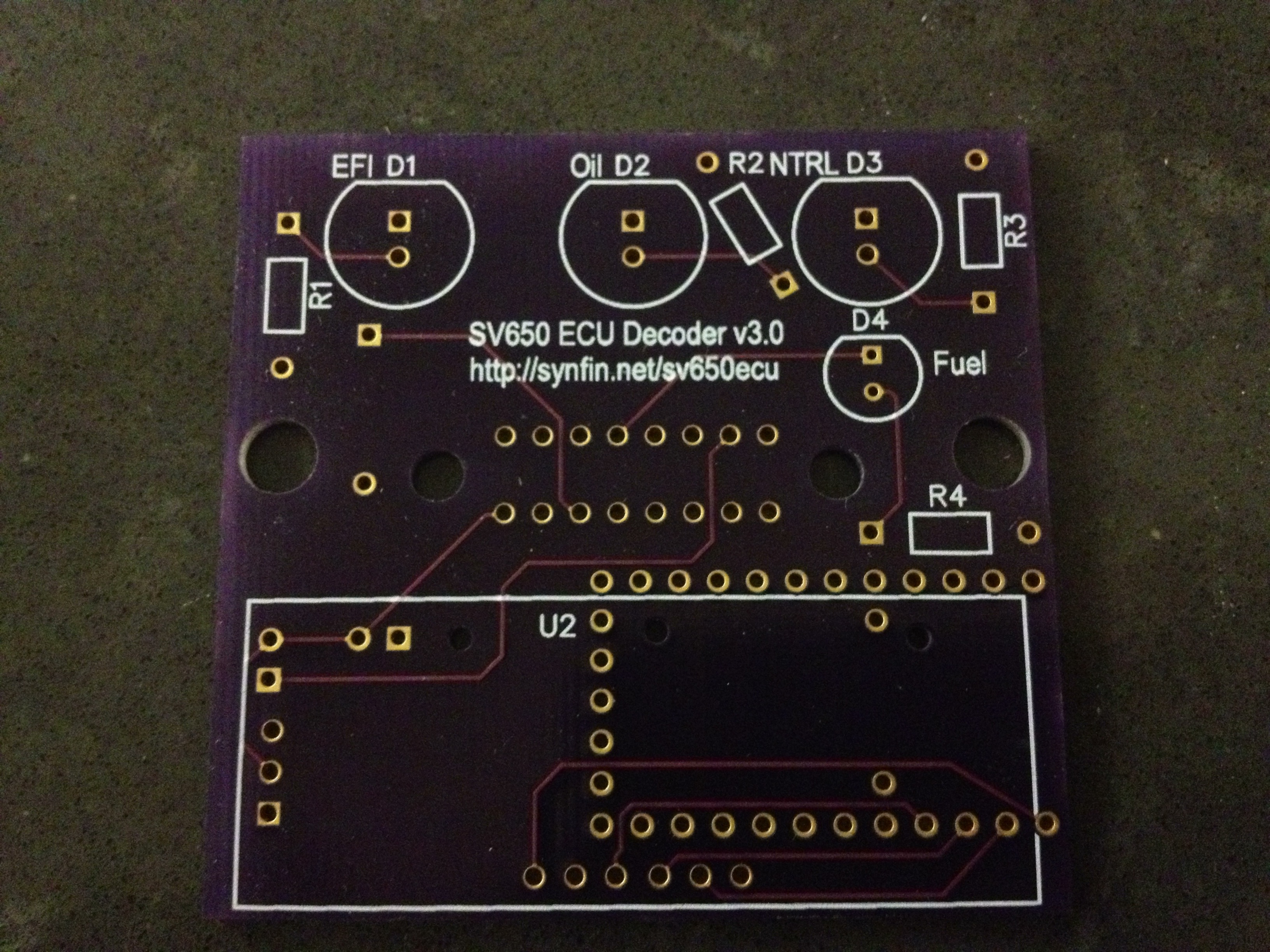
I recently got my first generation PCB in the mail from OshPark and I’m happy to say that the board works just like I had planned! I was able to do some basic testing using 10,000 step encoders, but due to the power of the Teensy 3.1 board and being able to use interrupt driven decoding there shouldn’t be any problem handling 100,000 step encoders if you so desired. The good news is that the board did a great job of reporting the position of the encoders to Sky Safari Pro running on my iPad via a wireless WiFi connection!

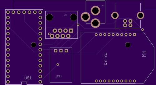
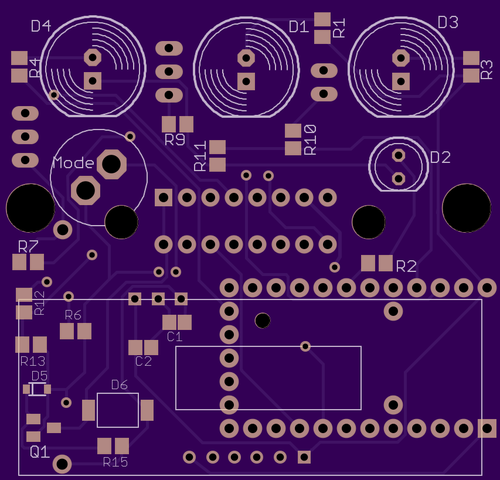
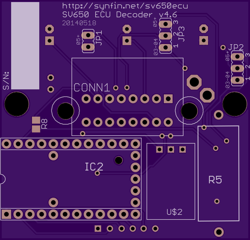
Renderings of the board I actually ended up using:

teensydsc-top-v0.5

teensydsc-bottom-v0.5

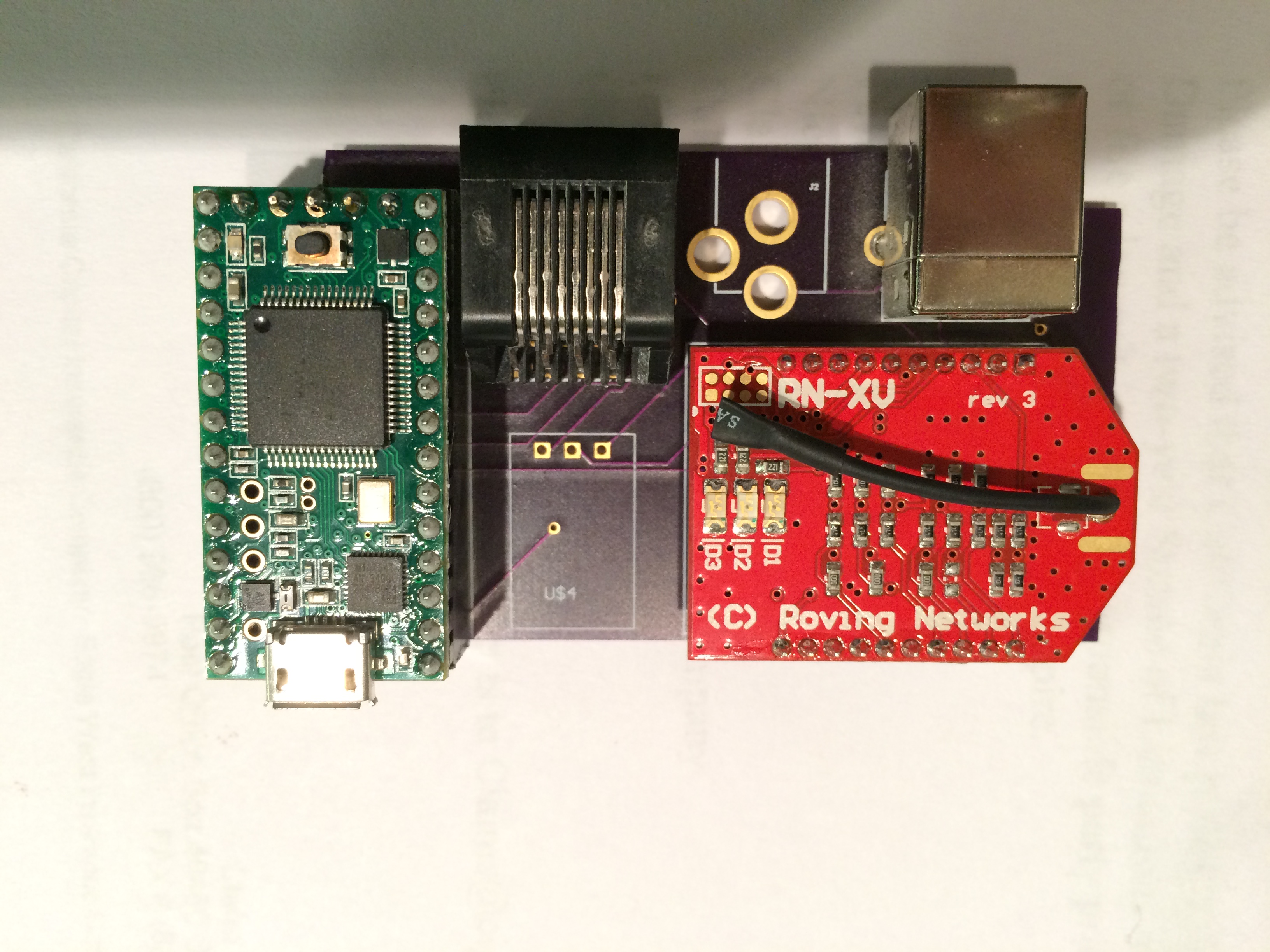
Photos of the board with the necessary components installed:

TeensyDSC Simple (populated) Top

TeensyDSC Simple (populated) Bottom

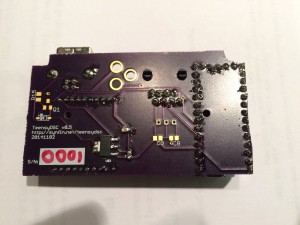
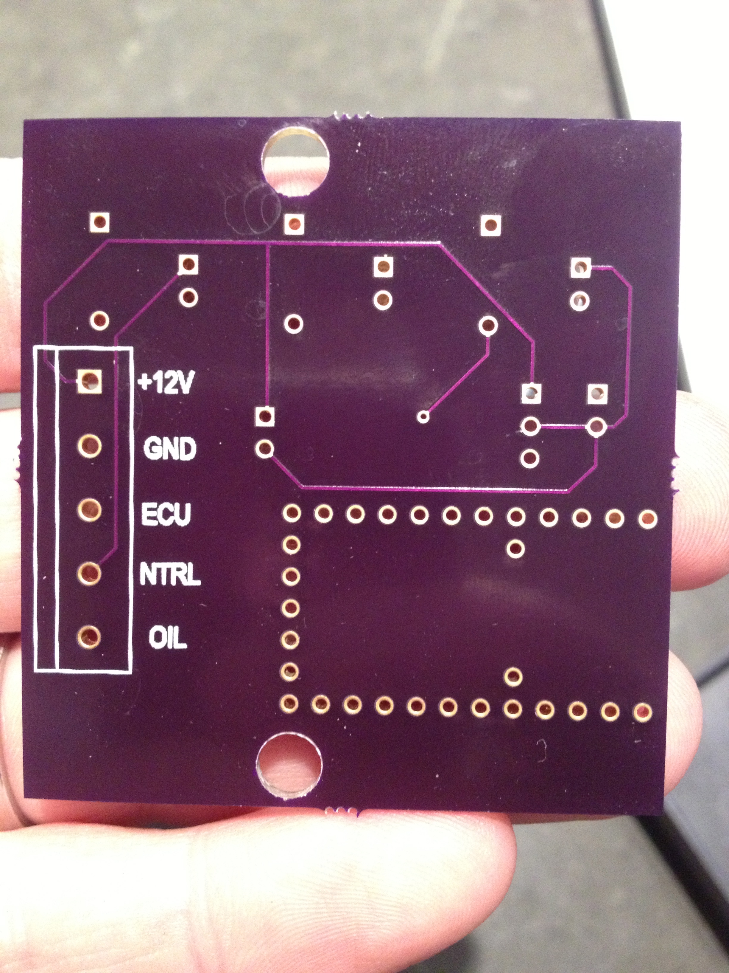
Notice there are some missing parts on the PCB.  That’s because so far I’ve only soldered on the parts necessary to power it via USB.  The missing parts are for powering it via 12V DC.

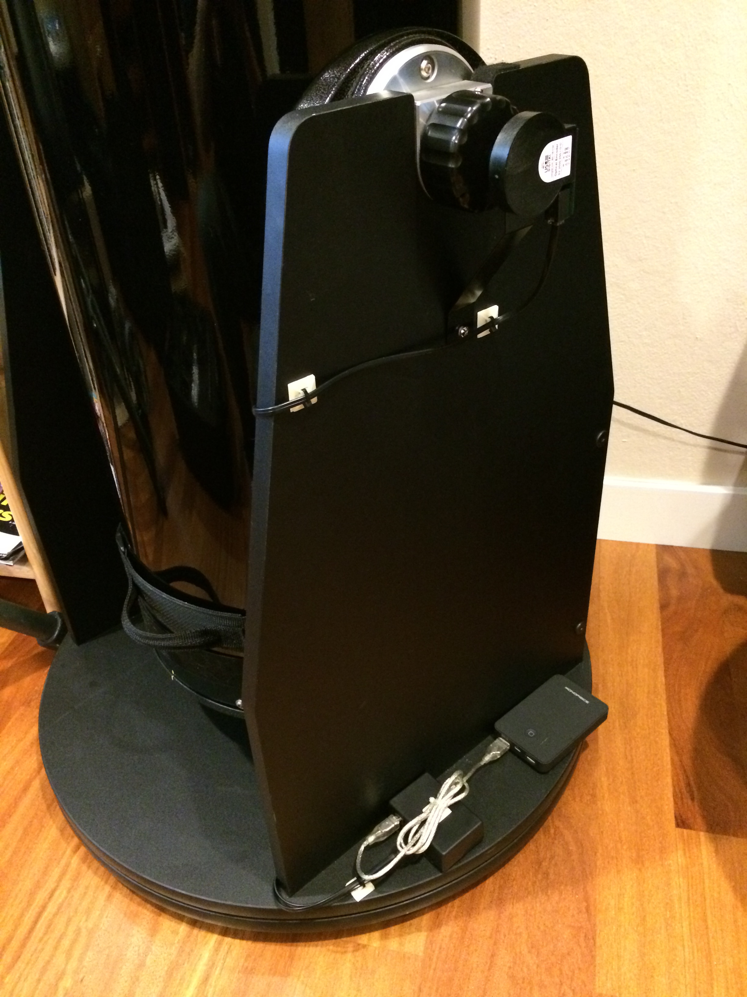
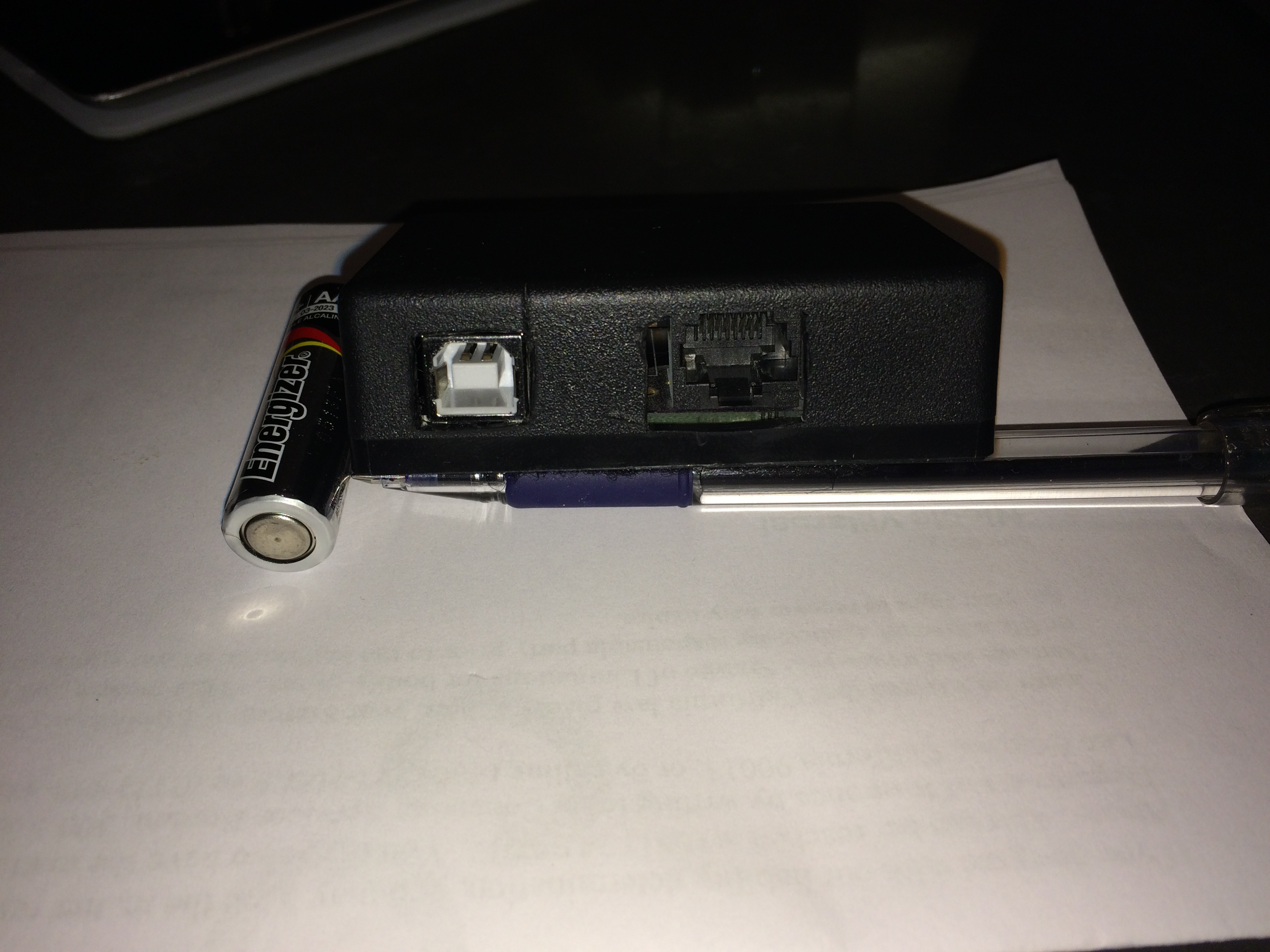
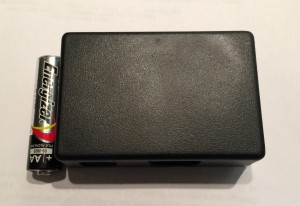
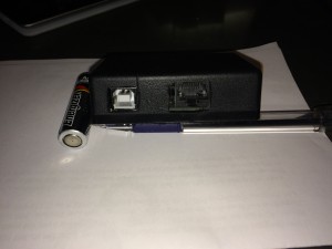
It also fits nicely in this small plastic enclosure I have:

2014-11-17 21.50.29

2014-11-17 21.48.12

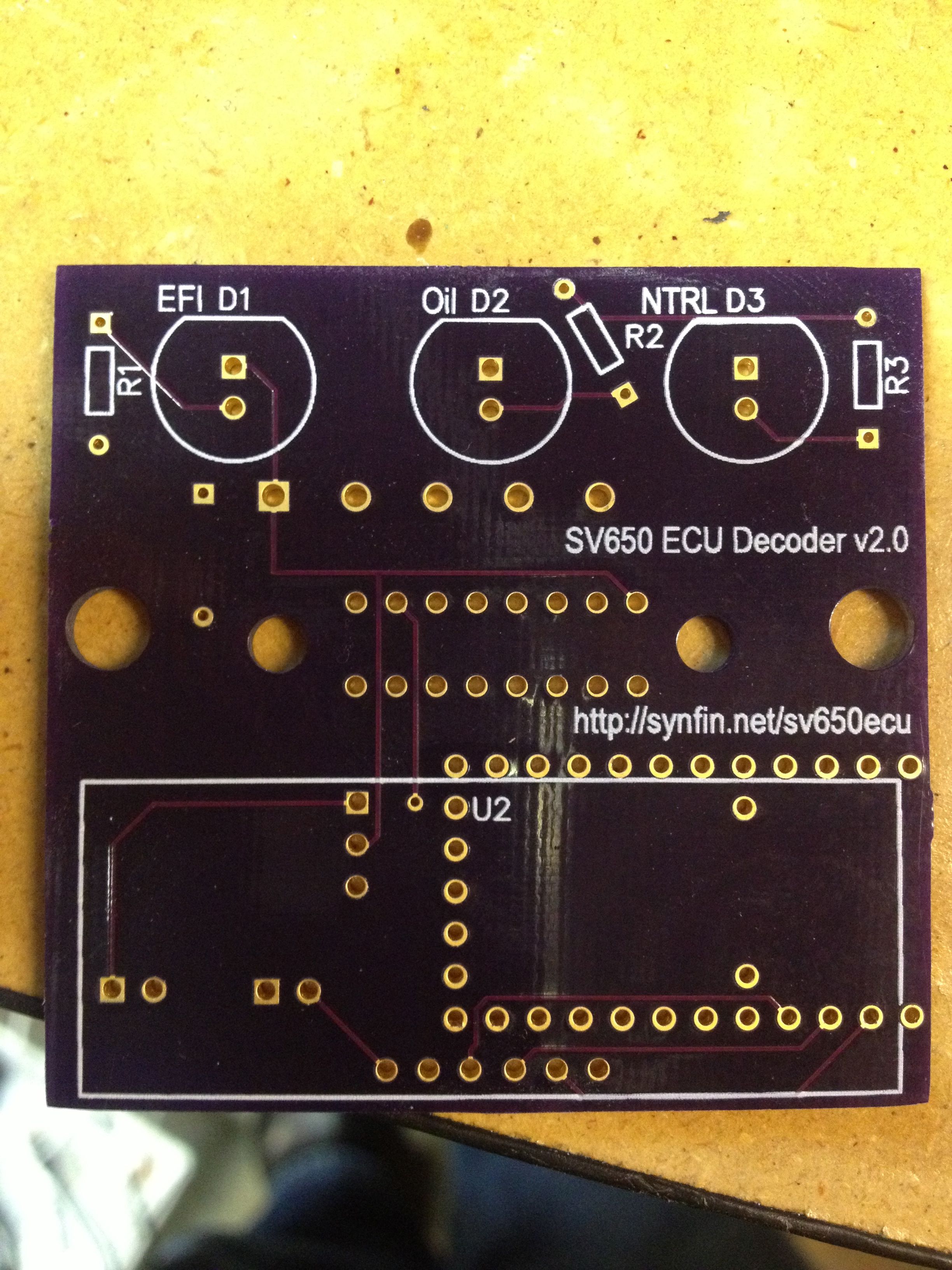
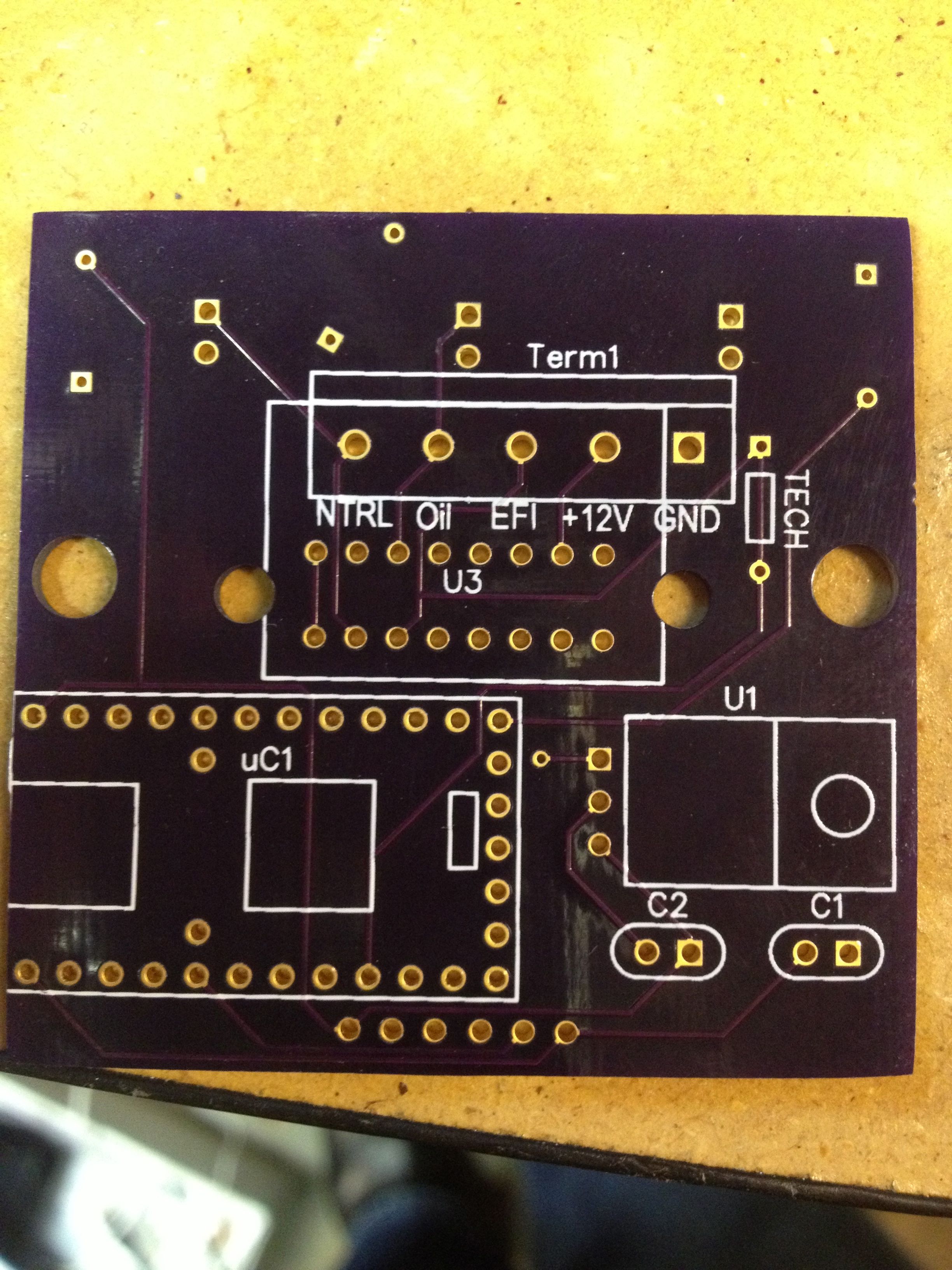
As you can see, this board is smaller and much simpler then the earlier board I designed. I did this because it wasn’t going to be possible to fit the original board in the small plastic enclosure I had picked out and most of the features I wasn’t actually going to use/need and I wanted to focus on getting the basic DSC features tested and working.

05/21/14

SV650 ECU Decoder v4.6 Design Finished

So I just ordered a few new boards from OshPark:

Front

Back

This was a major update which fixes all know bugs (many which are severe) and improves the protection of the circuit.

  • Switch to Murata 5V switching regulator.
  • LM7805 was overheating with heavy use of LED display in latest code
  • Add power MOSFET for reverse polarity protection
  • Add TVS diode for power/spike protection
  • Fix fuel/very low fuel indicator for 03-04 and 05+
  • Move EFI light off of pin 11 to allow interrupts to work
  • Move Mode switch to an interrupt pin
  • Add ground plane & clean up traces
  • Further improve battery voltage monitoring
  • Capacitors are now SMD too
01/25/14

v4.1 board design finished!

I’m happy to announce I’ve finished with the latest design of the SV650 ECU Decoder which has a number of improvements:

  • Add button for switching the display modes
  • Add support for detecting “very low fuel” on 2005-07 models
  • Improve battery voltage measurement circuit
  • Small tweaks to the layout and silkscreen

The board design has been sent to OSH Park for fabrication and hopefully I’ll get them in about 2 weeks.

Here’s a rendering of the new PCB design:

v4.1 Top

v4.1 Back

Update: So some testing of this board is showing some problems, including a possible problem which causes the Teensy board to be damaged, so I’m currently suggesting people not use it!

03/25/13

SV650 ECU Decoder Part 4: Third time is the charm?

Part 1 is here.
Part 2 is here.
Part 3 is here.

So my v2.0 boards were a complete dud.  Turns out some how I messed up the design and ended up wiring up the connector to the wiring harness backwards so nothing works.  Wasn’t a complete disaster- I was going to have to do another revision of the board either way, but it does slow things down. Continue reading

02/11/13

SV650 ECU EFI warning decoder/dash replacement

So I finally finished the design of my very first PCB and placed an order with OSH Park to get some samples. The basic premise is I needed a way to decode the data stream from my 2nd gen SV650 ECU to know when there is a problem with the fuel injection system with the race bike. Also, ideally, I needed a way to know what the specific error codes are.

Normally you do this with the stock dash, but I wanted to use my GPX Pro dash and didn’t want two dashes on my race bike. Unfortunately, the PCB on the dash is just one large unit (including the tachometer) and so there wasn’t an easy way to just use the parts I needed (a red idiot light and the LCD which displays the error code).
Continue reading