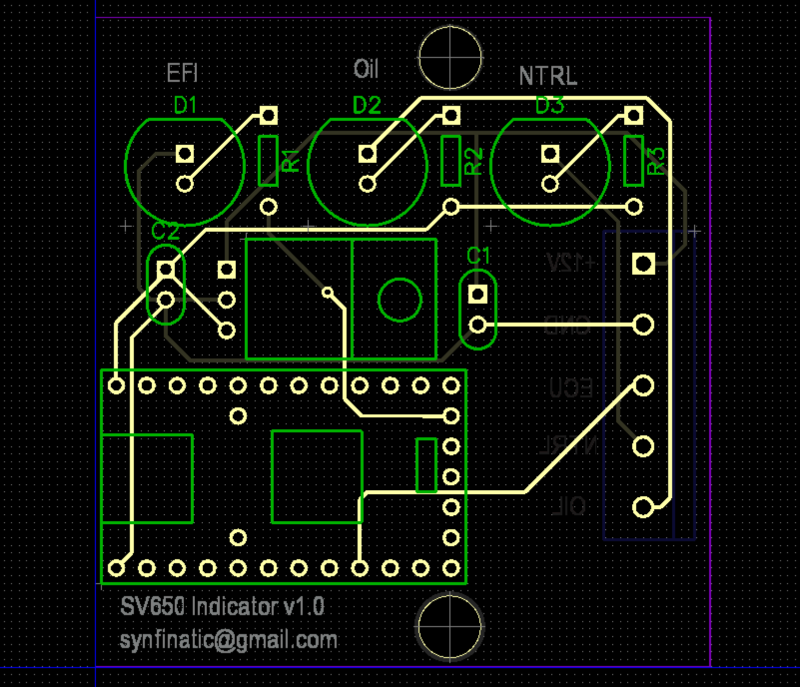
So I finally finished the design of my very first PCB and placed an order with OSH Park to get some samples. The basic premise is I needed a way to decode the data stream from my 2nd gen SV650 ECU to know when there is a problem with the fuel injection system with the race bike. Also, ideally, I needed a way to know what the specific error codes are.
Normally you do this with the stock dash, but I wanted to use my GPX Pro dash and didn’t want two dashes on my race bike. Unfortunately, the PCB on the dash is just one large unit (including the tachometer) and so there wasn’t an easy way to just use the parts I needed (a red idiot light and the LCD which displays the error code).
I did some research and found out that the ECU to dash communication is a simple 7800 baud serial data stream comprised of 8 byte messages sent every 10 seconds. I ended up doing a quick prototype with an Arduino Uno board I had laying around:
Suzuki SV650 ECU/FI Warning Decoding via Arduino from synfinatic on Vimeo.
Once I got it working I quickly realized two things:
1. The Arduino board is too large and unwieldy to use on the motorcycle.
2. The Arduino uses it’s serial line for the USB which meant I had to do 7800 baud completely in software which used up a lot of CPU time.
I finally ended up picking the Teensy 2.0 board by PJRC. It’s about half the cost of an Arduino, a quarter of the size and has hardware serial support for both USB (good for logging) and on pins (good for listening to the ECU).
In the past I had played around with Eagle, but I always found it confusing and hard to use. This time I decided to try out DipTrace. Overall, I found DipTrace much easier to use, but it uses Wine under Linux/OSX and so it can be a bit buggy which really removed the polish from what overall seems to be a great app.
In the end I ended up with this board which is just a little bigger then 2×2″:
The biggest surprise and hardest part of the whole project wasn’t writing the code for the Teensy or designing the circuit, but rather trying to find a nice enclosure for the board and then designing the board to fit it properly. Realizing you have to think in 3D space (I had to lay down the LM7805 power regulator so the cover would fit!) and figuring out where the mounting holes should go (the spec sheet for the enclosure was painfully obtuse about this).
Things I’d like to do in the next version:
1. LED display for printing EFI error codes so you don’t have to plug in your computer
2. Add support for displaying water temp (I’m using my GPX Pro for this, but it’s included in the data stream)
3. Find a source for the dash wiring harness connector so you don’t have to splice your wiring harness
4. Read tach signal (again I’m using GPX Pro so this is pretty redundant for my needs)


Pingback: SV650 ECU Decoder part 2 | Syn Fin dot Net
Pingback: SV650 ECU Decoder Part 5: They’re here! | Syn Fin dot Net